Introduction
Wagon Tippler is capable of receiving, clamping and tippling BOX/DFC wagons and other types used by Railways. The wagon tippler empties the wagons by inverting them through an angle of 160º (Max).
Components of Wagon Tippler
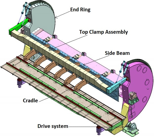
The wagon tippler consists of the following main components:

- Cradle
- End rings
- Side Beam (Side Bolster Beam)
- Top clamp assembly
- Drive system
- Wheel Grippers
- Wheel Chockers
Cradle
The cradle is a frame of table, comprising two main girders, braced together. Two rails are to be fitted on the main girders on which the wagon is placed. The cradle has sufficient length to accommodate one broad gauge open wagon (any of the types used by Indian Railways).
End Ring
A pair of end rings is trunion mounted for the purpose of rotation.
The centre of the end rings is reinforced to carry the trunnion shafts; each of these shafts in turn is supported on pivot bearing resting on foundations. On each ring is attached an arm known as “toe” that carries the slotted bearing and supports the cradle and wagon during operation. Part of end ring is filled with concrete to provide the counter weight. This counter weight reduces the moment of work required during the tipping on the wagon.
Gear sectors are mounted at the periphery of each end ring, which is driven by pinion mounted on counter shafts.
Side Beam (Side Bolster Beam)
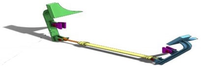
It is located on side beam to prevent jerk during motion of the wagon in tippling operation. It is Hydraulic cylinder actuated device operated through solenoids by PLC O/P. The side support clamp is activated simultaneously with wheel gripper operation after placement of wagon on cradle at exact location. This input is taken to PLC through Magnetic Limit Switch.
side support is so designed that it has a facility of forward /backward movement, such that it should be able to move & touch the wagon without applying any pressure on the wagon side wall.
Top Clamp Assembly
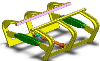
This structure is designed to support the wagon from the top face in the tipped position and mainly consists of one bolster beam, two clamp arms & six transfer beam & hydraulic cylinders.
The top bolster beam is fitted with end ring of wagon tippler with the help of clamp arm & four nos. of hydraulic cylinders. These hydraulic cylinders operate the top bolster beam to rise & lower the top clamps & bring them in contact with wagon’s top faces.
This will facilitate proper clamping of different height of wagons and also bulged wagons.
Drive System
Wagon tippler is operated with both side drives. The drive unit consists of two Hydraulic Motors connected to input side of helical gear box through geared coupling. The power is transmitted to end rings by two pinions (mounted on drive shaft) dedicated to each end ring. The sector gear is bolted on periphery of end ring through fit bolt. The pinions on drive shaft are engaged to sector gear for getting rotation of end ring. The hydraulic motor is driven from hydraulic pressure and flow generated from a power pack positioned at drive pit.
Wheel Grippers
These are located on tippler table (cradle) to prevent inadvertent motion of the wagons during tippling operation. These are Hydraulic cylinder actuated device operated through solenoids by PLC O/P. The Wheel gripper is activated after placement of the wagon on tippler table.
Wheel Chockers

These are located at the in-haul and out-haul track side to prevent accidental rolling of the wagons on the tippler table (cradle). These are Hydraulic cylinder actuated device operated through solenoids by PLC O/P. The Wheel chocker is activated when SAC is moving with the coupled wagon (single wagon) towards tippler table.
Wagon Tippler Operation in Auto Mode
Operation of Wagon Tippler in Auto mode through a Cycle Push Button provided in the Control Desk. This cycle push button operation is effective after SAC reaches at DD position and complete operation of the Wheel Chocker, Wheel Gripper, Side Support and Weigh Bridge
In the cycle operation, once the SAC places the loaded wagon over the wagon tippler platform (exact placement is ensured automatically by Magnetic Limit Switch input to PLC), the control desk operator will give an input command to PLC by pressing push button (assigned gross weight) which in turn gives an output command to weigh bridge panel for taking gross weight.
After taking the gross weight by Weigh Bridge, an input command will be given by Weigh Bridge panel to PLC which in turn will give an output command to glow an indication lamp showing gross weight taken is over.
The system will be interlocked in PLC logic with the feedback of hydraulic pressure switch for wheel gripper, wheel Chocker, side clamp and top clamp device. If all the above inter-locked are satisfied, then PLC will give an O/P for ready tippling lamp and it will start glowing showing that the Tippler is ready for tippling.
Now press the push button for blowing the Siren to warn the people around the wagon tippler. After blowing of Siren, press the cycle operation push button and thereafter wagon tippler cradle shall start raising. After certain time interval from starting, the top clamping devices start moving to clamp the wagon. This time lag is based on approx. 10 degree of rotation of tippler.
The top clamping device will clamp the wagon at about 65 degree of rotation of wagon. After fully clamp of clamping devices with the wagon, the PLC receives an input from the pressure switch at about 70 degree of rotation. On receipt of the input, PLC allows the raise operation to continue and the tippler is raised up to 135 degree/set degree (as per requirement and on the basis of trial run, the degree of max. Raise is set) for complete discharge of coal from the wagon and stops through the raise limit switch.
The degree of rotation is set/ adjusted by screw cam limit switch. One contact of this limit switch is used to stop the WT raise/lower contactor and another contact of same pad is used as an input to PLC for withdrawing raise command. On completion of the raise operation, there will be a pause of 5 sec. and thereafter the wagon tippler will start lowering.
During the lowering operation as soon as the wagon comes to 80-degree position, the de-clamping operation starts and the lowering operation is stopped through the lower limit switch and the tippler comes to normal rest position and in the same time the clamps goes back to its normal position.
Wagon Tippler Operation in Manual Mode
In this mode of operation, by actuating the start/stop push buttons provided in the control desk, the individual equipment can be started in sequence one by one. There are 2 Push Buttons provided on Control Desk- WT Raise & WT Lower.
When the WT Raise is pressed, Wagon Tippler starts rotating and it will stop when the Raise Screw Cam Limit Switch actuated. There is no pause time define in this mode.
When operator will press the ‘WT Lower PB’ then only the Wagon Tippler will come down to its lower position. In this way the tippling cycle is completed. The interlocking of individual equipment with its preceding equipment is taken care by PLC.
Wagon Tippler Operation in Local Mode
In this mode of operation, only the maintenance of the equipment can be taken up and can be operated from local control station provided in field. This mode is effective only when selector switch provided on the control desk is kept in local position without any interlocking with other equipment.
RELATED SEARCHES:
